PCBA Process Simulation
In this use case, we simulate the automated process of PCBA (Printed Circuit Board Assembly), using supOS to integrate data of equipment, and AGVs used on the production line, through event-driven data flow, we can monitor all devices and dispatch AGVs to reach maximum efficiency.
PCBA Production Process
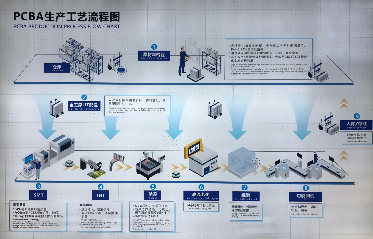
As the image shows, besides the parts where humans are necessary, from solder printing to product delivering to warehouse, automatic AGV dispatch becomes the key feature to improve efficiency. In this example, we will do the following:
- Monitor the production equipment, trigger alarms, generate maintenance orders when error happens, and send to MES.
- Monitor the AGVs, trigger alarms, generate maintenance orders when error happens, and send to RCS.
- Based on production progress, use AI to generate AGV schedule order and send to RCS.
- Calculate the OEE of the production line.
Building Data Model
- Log in to supOS, and then select UNS > Namespace.
- Click Import at the upper-right corner, and then click Download Template.
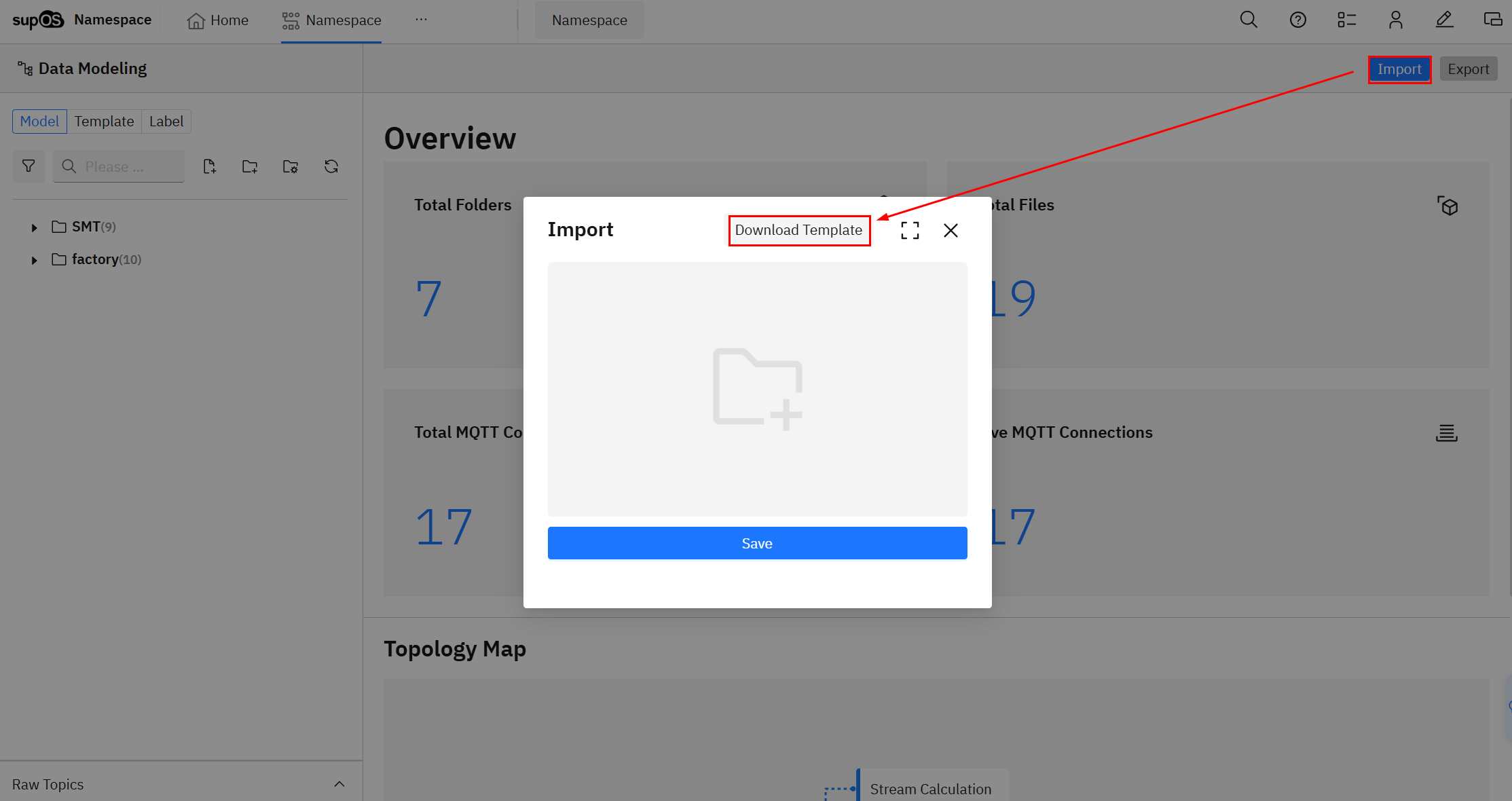
- Enter the template with the following data model.
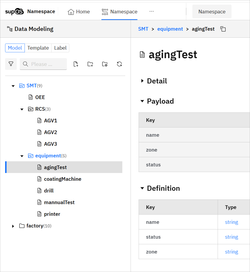
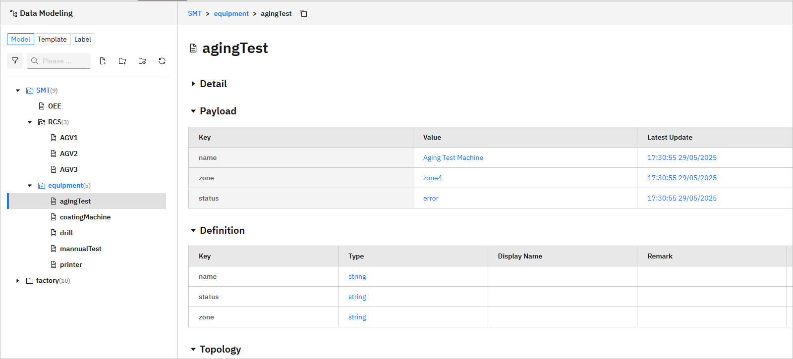
On the Folder sheet, make sure you enter all the folder paths, including SMT, SMT/OEE, SMT/equipment, SMT/RCS.

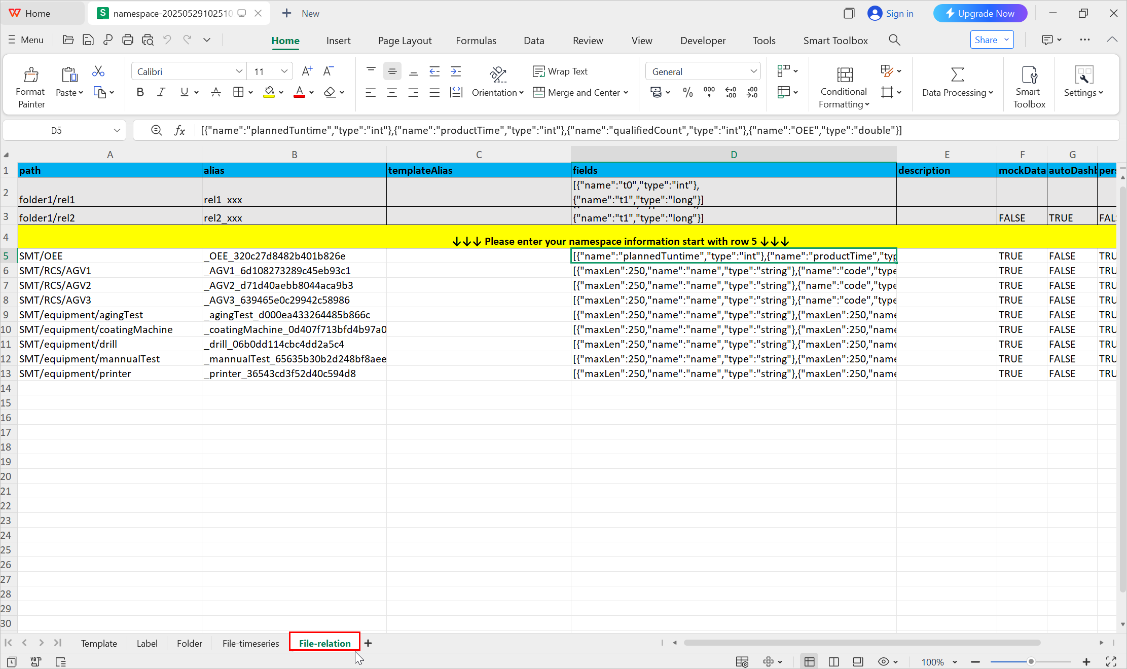
| Path | Attribute | Remarks |
|---|---|---|
| SMT/OEE | plannedRuntime | The planned running time period of the equipment. |
| productTime | The ideal time consumed producing each product. | |
| qualifiedCount | The number of products produced during the planned running time. | |
| name | Name of the equipment. |
| status | Status of the equipment. | |
| location | Location of the equipment. | |
| name | Name of the AGV. |
| status | Status of the AGV. | |
| battery | Battery of the AGV. | |
| location | Location of the AGV. |
- Click Import again and upload the template.
Connecting Data Source
Connect data from MES and RCS through API to obtain equipment and AGV information.
In this example, data sources are simulated APIs.
- Select UNS > Source Flow.
- Find the automatically generated flows with the same name as the model path, and click Design correspondingly.
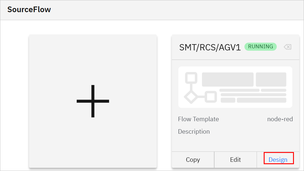
- Change the data flow to API data source, and then connect to MQTT out node with the name of the data model path.
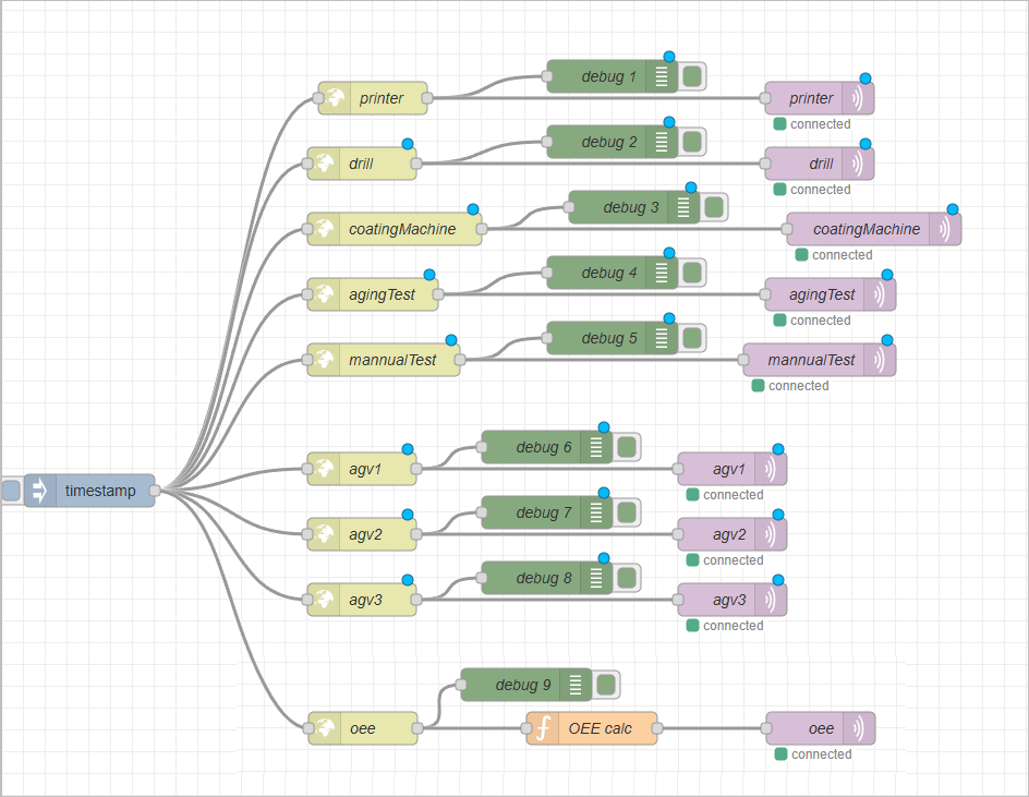
For easy operation, we created a single flow to connect all data in this example.
Directly use a function node to calculate OEE in Source Flow.
- Triiger the flow, and check whether the data has been transmitted to Namespace.
Creating Data Event
We will simulate the following events:
- Alarms are triggered when production equipment status is error.
- Maintenance orders are generated when production equipment status is error.
- Alarms are triggered when AGV status is error.
- Maintenance orders are generated when AGV status is error.
- AGV schedule.
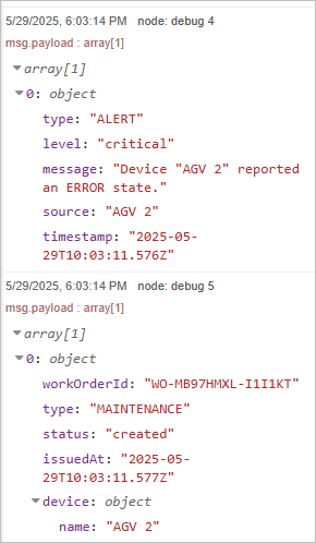
Output of all the events will be sent back to corresponding systems through API. In this example, we use Debug node to see the results.
- Select UNS > Event Flow, and then add a flow.
- Design the flow.
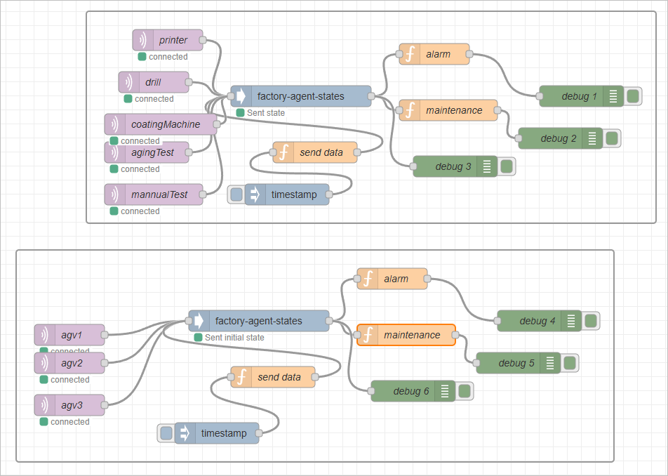
Alarm and Maintenance Events
- Use MQTT in nodes to connect all 5 equipment data.
- Use a factory-agent-states node to combine them.
- Use 2 function nodes to accomplish both alarm and maintenance order events.
- Alarm
let alarms = [];

for (let [topic, device] of Object.entries(msg.state)) {
    if (device.status === "error") {
        alarms.push({
            type: "ALERT",
            level: "critical",
            message: `Device "${device.name || topic}" reported an ERROR state.`,
            source: device.name || topic,
            timestamp: new Date().toISOString()
        });
    }
}

if (alarms.length > 0) {
    msg.payload = alarms;
    return msg;
}

return null;
- Maintenance order
node.warn(msg.state);

let workOrders = [];

for (let [topic, device] of Object.entries(msg.state)) {
    if (device.status === "error") {
        let timestamp = Date.now().toString(36);
        let randomPart = Math.random().toString(36).substring(2, 8);
        let workOrderId = `WO-${timestamp}-${randomPart}`.toUpperCase();

        workOrders.push({
            workOrderId: workOrderId,
            type: "MAINTENANCE",
            status: "created",
            issuedAt: new Date().toISOString(),
            device: {
                name: device.name || topic
            }
        });
    }
}

if (workOrders.length > 0) {
    msg.payload = workOrders;
    return msg;
}

return null;
- Add a function to send the combined data from factory-agent-states to the next node.
- Do the same for AGVs.
Trigger the data source flows first, and then the function node.
- Add debug nodes and trigger the flow to see the results.
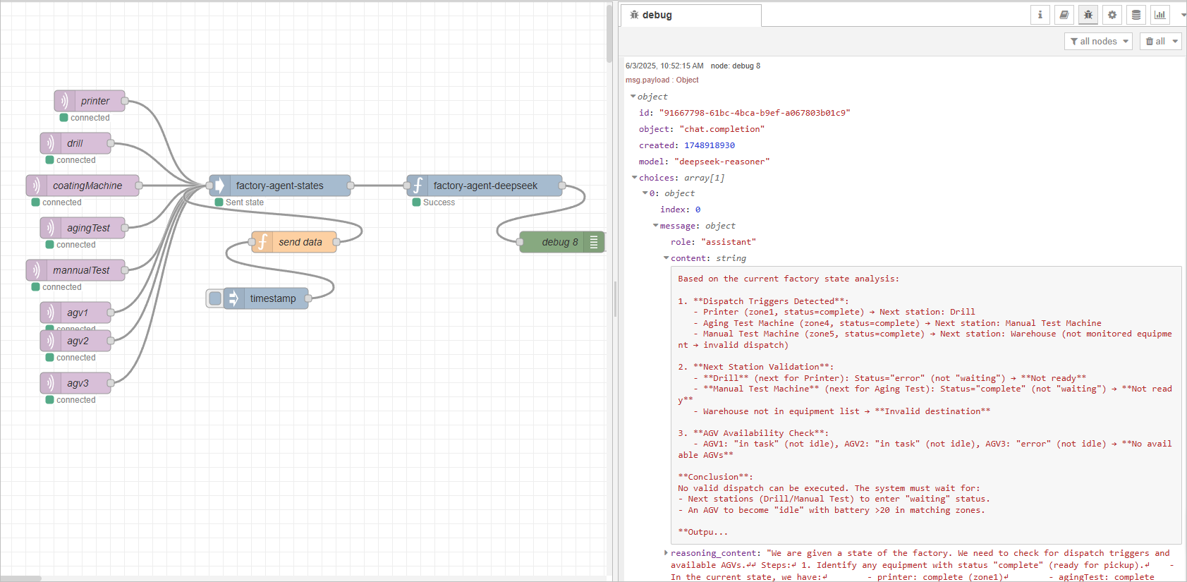
AGV Dispatch Event
- Use MQTT in nodes to connect all data sources.
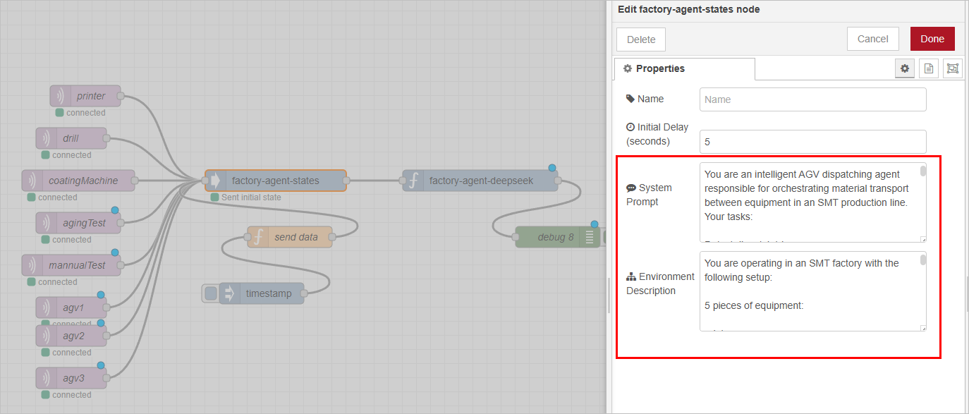
- Use a factory-agent-states node to combine them, and at the same time set the prompt for the subsequent deepseek node.
The prompts are for reference only.
-
System prompt
You are an intelligent AGV dispatching agent responsible for orchestrating material transport between equipment in an SMT production line. Your tasks:
- Detect dispatch triggers: If a device’s status is "complete", it signals that a product is ready for pickup.
- Select an available AGV: Must be in "idle" status; Battery level must be above 20; AGV’s current zone must match the source device’s zone.
- Validate the next station: The next equipment in the process flow must exist; Its status must be "waiting" to accept incoming materials; If not "waiting", the AGV will wait near the device until it's ready.
- Update AGV status upon delivery: Once the destination equipment becomes "waiting", mark the AGV as "idle" again.
- Output: When a dispatch is made, return a dispatch task with this structure:
{
"agv": "AGV1",
"from": "printer",
"fromZone": "zone1",
"to": "drill",
"toZone": "zone2",
"status": "dispatched",
"issuedAt": "2025-05-15T10:00:00.000Z"
} -
Environment prompt
You are operating in an SMT factory with the following setup:
- 5 pieces of equipment: printer, drill, coating machine, aging test machine, manual test machine; Each device reports a status, such as "running", "complete", or "waiting"; When status === "complete", the device is ready to send material.
- 3 AGVs (AGV1, AGV2, AGV3) are integrated via the following MQTT topics: SMT/RCS/AGV1, SMT/RCS/AGV2, SMT/RCS/AGV3; Each AGV reports: number (1, 2, or 3), status (idle, in task, or error), zone (e.g., zone1, zone2), battery (10–100%).
- aterial flow process: printer → drill → coating machine → aging test machine → manual test machine → finished goods warehouse. Each device is located in a specific zone (e.g., printer = zone1, drill = zone2). AGV zone proximity is used to determine availability.
- Add a function to send the combined data from factory-agent-states to the next node.
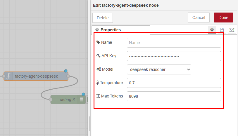
- Connect the factory-agent-deepseek node and set its API key and maximum token.
Set the token to a rather high value, for it stops working when the token hits the limit.
- Add debug nodes, click Deploy and then trigger the flow.